• Welcome to BiplaneHangar.com, the only FREE online community 100% dedicated to biplanes and the people that love them!

    You create the content here, you shouldn't have to pay to access it! Take a look around, register and jump right in when you're ready.

    PLEASE NOTE: New account verification emails are being sent to SPAM folders, please check there after registering if you feel you haven't received a verification email.

    There is a Contact Us link at the bottom of every page if you have a question about BiplaneHangar.com.

    Thank you and WELCOME!

Ryan’s Model 12 Build.

Hey Bart hope you are feeling better. Did you loose your voice when sick? I just got home from overseas and my wife is sounding worse than Marge Simpson’s twin sisters…hoarse and flu like symptoms.

I have not had a chance to investigate further what to do with this spar. The next few days off I am involved in major fundraiser for our local Heart and Stroke foundation so I won’t have time to get my inspector to give me a verdict.

I did buy a Douglas Fir 10 foot 2x6 at my specialty woods store…but I have to determine if it is suitable…the good news is that it is very old growth and the grain pitch is great once resawn to 1x5.

All for now…


PXL_20260530_195422901_Original.webp
PXL_20260530_195451061_Original.webp
 
At least you have options in hand.

Can that spar be positioned so the thicker area can be below the knot and the thinner area above it? That would put the knot in compression under positive g’s and tension under negative g’s which are typically less.

Feeling a little better today but still dealing with system instabilities.
 
Unfortunately the spar from the wood kit i have is cut and drilled as is.. The orientation is fixed.

Oddly the knot only shows on the aft face of the spar..the front face looks perfect as if nothing is there at all on the aft side.

The location is outboard of the I strut.

The cheap side of me says this is going to be fine. The knot doesn't go all the way through, and by the time it gets soaked with thinner Epoxy varnish that's going to soak in at least an eighth of an inch it's a nothing burger. Especially since it's not 3/8 of an inch in all directions. It's about a quarter inch on one side and 13/32 the other side... But the other side of me says this should be pristine wood...

Heck, there's probably many Pitts flying perfectly okay with wood spars that look pristine but then have a big ass pitch pocket somewhere inside them....
 
The Saga continues....

If you want some heavy reading and you've got an engineering background or an analytical mind, check out ANC-18 design of wood aircraft structures...1944.

If you don't care so much for the math and you're interested in learning more about wood in aircraft, then check out ANC-19 bulletin, Wood Aircraft Inspection and Fabrication.

Both of these are free downloads on the internet...

To the data..ANC-19 gives perfect descriptions of all the woods, and their allowable defects. Along with lots of other information, including even how to make tools and machinery for working with aircraft wood.

It also gives the definition of what constitutes a "Tight Knot" and defines the difference between diameter and size... Two different definitions.

MIL-S-6073 defines material and workmanship for aircraft spruce and references ANC-19.

These two documents are easy reading. A

NC-18 is for the engineer and though heavy reading has hidden gems of very interesting information. I'm going to have to read it a few more times for it to sink into my thick brain.

What I have learnt from all this is that ANC-19 Wood Aircraft Inspection and Fabrication... Is by far the most useful in determining what wood can be used and wood that should not be used.

The conundrum...


The analysis of the spar that was supplied in the wing kit does meets the specifications of ANC-19.

But I have now started down the path of producing a replacements spar, and so far it also has not given me reason to be rejected by ANC- 19.. however, the milling procedures are not done and I still need to calculate the specific gravity of the Douglas Fir at its current moisture content to determine if it's within the specifications outlined.

This is definitely home building and by no means would I recommend anything I'm doing to those others thinking of doing the same thing. I am being careful and making sure that what I'm doing has a written reference to justify the result. Anyone thinking about doing this has to walk on their own two feet and do their own due diligence themselves...


My new spar started out as a 2x6" x10' of Douglas Fir clear Vertical Grain.

The quarter sawn grain angle was approximately 28°. Because I need to mill a 1x5", I decided to resaw the 2x6 down to 1x5 and also improve the grain angle by taking the 1x5 out of the 2x6 on its diagonal....

I then had to make a flat surface using the jointer followed by making a 90° edge on the jointer and then bring down the thickness on the planer...

Unfortunately the woodworking tools are old and haven't been used for a long time as they are idle at my dad's workshop who has passed away in 2018. So 4 hours of correcting and adjusting machinery followed by 2 hours of woodworking created a spar blank.

Now for the fun part, the pictures and video.
PXL_20260530_163834342.webp
PXL_20260608_181408087.webp
PXL_20260608_191747207.webp
PXL_20260608_200110902.webp
PXL_20260608_205010995.webp
PXL_20260608_211939806.webp
PXL_20260609_014325624.MP.webp
PXL_20260609_015618389.webp


Video

Milling Douglas Fir
 

Attachments

  • PXL_20260609_015627381.webp
    PXL_20260609_015627381.webp
    253.1 KB · Views: 42
Last edited:
I should point out the first picture is the very first 2x6 I pulled out of the pile at the supply yard. Look at the quarter sawn grains per inch...

I thought I'd struck gold...

But sure enough it had a big fat knot on one edge. definitely usable for other shorter pieces if needed.
 
Last edited:
I've never seen douglas fir with grain that tight but I've never gone looking for spar material, only bought 2x's at the lumber yard. I'd see old growth fir in old houses when I was a remodeling contractor, we'd save whatever we could and try to reuse it. You should be back moving along on the top wings any day now.
 
Thanks Bart.
The supplier I found the material at deals with custom wood for the specialty crowd. They even have material from an old Welland Canal lock that runs from Lake Erie to Lake Ontario.. The timbers in the lock door were huge!

Before I go any further on my home built DF Spar, I need to get the blank weighed. I do not own a scale that will read accurately, so pausing on process today. I am fighting a wicked cold; summer colds are no good. Day 4 seems to be the worst yet.
 
I figure here is a good place to keep my records of my spar building adventures.
So sorry for the math dribble....

My piece of Douglas-Fir measures 290.6cmx14.41cmx2.23cm for a volume of 9338.23 cm3.

The mass of the Douglas Fir is 5.4896 Kg.
Moisture Content = 10% (to be confirmed by using a second moisture meter; I don't trust mine 100%)

Doing the conversions it equals 12.1 lbs and volume of 0.3298 ft^3

Density = 36.7lb/ft^3 and a specific gravity of 0.588 at 10 % moisture.

Using Table 2-4 from ANC-19 I must adjust for the correction factor to calculate what my stick of Douglas-Fir would be if it was "Oven Dry" which shows a Minimum Permitted Value i need to be better than.

The constant for a 1% change in moisture is 0.129 for Pound Cubic foot.
36.7 - (10x 0.129) = 35.41 lb/ft^3

Then use ANC-19 Table 2-5 to get the SG of your corrected density for Oven Dry. You interpolate the specific gravity between 35 and 36 pounds per cubic foot and I come up with 0.5675 SG.

The Minimum specific gravity and Pounds per cubic foot to be used in aircraft for Douglas-Fir is: 0.45 SG and 28.1 lbs/ft^3

ANC-19 also lists averages of each for Douglas Fir at 0.512 SG and 31.9 lbs/ft^3

My wood is good!!!!

Now just as an analogue. I also took the weights of the spars that came in my wing kit.

Each Spar weighed within 5 g of each other.

When I cut out the spar from my material and have all the milling done for the holes I'll weigh it and see how it compares to the ones in my wing kit.


PXL_20260611_201025761.webp
PXL_20260611_201607661.webp
 
Last edited:
Today was slow...feeling better and then feeling worse.

Took the time to get the taper cut done one the spar blank using my table saw, and then made flat with the Bailey #7.

The pitch pocket is placed right on the cut so that i could get a good cross section view.

Probed the pocket with the 0.030 ER70S2 mig wire and it goes in half the thickness of the board.

So when the bevel on the thin side is cut, the pitch pocket will be gone.

So far so good.

PXL_20260612_191920225.webp
PXL_20260612_210303447.webp
PXL_20260612_212135430.webp
PXL_20260612_212147296.webp
PXL_20260612_215809044.webp
PXL_20260612_215835868.webp
PXL_20260612_215947142.webp
 
Hi All.

With the school year wrapping up and work schedule increasing, home improvements demanded…getting back to the Douglas-Fir spar has been slow. Just itching to get the next steps done to see if something appears that makes it not usable… curiosity is killing me lol.

ANC19 outlines very clearly what is allowed. Some definitions are also clearly stated and they are not intuitive in the normal sense when it comes to dimensions of lumber..

All this reading has led me to believe that my original spar that came in the wood wing kit, though not pristine with its small knot outboard of the I strut; is serviceable as far as I can tell from everything I’ve read in ANC19. It isn’t a spike knot, it is in the middle half of the spar, and the diameter is less than 0.250 inch.

So then you may ask why am I milling a new spar and wasting time…well because those that I talked to about my original spar also were wondering if it was ideal to use and weren’t comfortable like me.

So where does that leave me with the new home built spar?

So far it has been turning out to exceed my expectations.

I left the depth of the spar proud while milling, and that is why in the previous post the pitch pocket was not removed.

I wanted to get the I-strut hole drilled before beveling the edges to fit the rib openings: a; so the drill bit was less likely to walk on the flat surface. b; if the hole had any tear out, that would get cut off when the bevel was cut. The hole was “drilled” on my mill with lots of time taken to get the spar plumb to the mill. I used a 15/64th Brad point mill bit that was wicked sharp order from Amazon for not much more than buying a regular Brad point.

This worked out as planned.

After I-strut hole was drilled I cut and beveled the spar to match the kit spar.

Then I used pins in the I strut holes to align the length and mark the wing tip, root, and flying wire holes.

The holes were then drilled and checked for alignment using the original spar as the template and cross checked to HP wing drawing and Mid America plans.

Wood defects discovered thus far.

The pitch pocket is all but gone. It was cut off during the bevelling of the edge one edge.
A new, very small, oval knot has been discovered on the beveled edge. It measures 1/16in diameter, which AN19 states can be ignored on it’s own, but would need to be counted if there was a cluster of small knots in an area.

What is left to do…cut the scarf joint, and wing tip profile. Once those are done, I am going to get so more eyes on my homemade spar and discuss it’s validity, and if mine or the original are trash or usable, may the best spar win.


PXL_20260613_201048854_Original.webp
PXL_20260626_152657723_Original.webp


PXL_20260626_152639812_Original.webp

exported_98CD83F9-74A5-498B-B247-223A59825E00.webp

PXL_20260627_214230989_Original.webp
PXL_20260627_214921535_Original.webp
PXL_20260628_133804789_Original.webp


What is left of pitch pocket after final dimensions cut:

PXL_20260628_134135796_Original.webp
PXL_20260628_134548259_Original.webp
 
Last edited:
Today I fooled around with making a spar scarf jig.
I used the kit spar as the template and Mid America plans to confirm the splice is 7 degrees.

Had to make a new base plate for the router to traverse the jig box.
Used some scrap spruce to check the box and discovered some important tips… first, don’t use a 3/4 inch router bit..too aggressive and it was hard to control hand routing…I used the 1/2 inch bit, until I was close, and then switched to the 1/4 bit for fine control to feather the edge…took a while, but the results were in the pudding….

I also discovered when switching to the 1/4 inch bit, that I saw the scarf joint was not uniform…one side was slightly higher than the other..my jig box was slightly canted. I fixed that by shimming the spar on the one side 0.020.

Overall, pretty pleased with how it turned out. I didn’t keep cutting down with the quarter inch bit all the way. I stopped before it was a true feather edge and then finished it using a hand plane. Now have a very nice feathered edge that should make for a very good splice joint.

PXL_20260628_161131685_Original.webp
PXL_20260628_205040826_Original.webp
PXL_20260628_162957034_Original.webp
PXL_20260628_204330714_Original.webp
PXL_20260628_193903953_Original.webp
PXL_20260628_210148495_Original.webp
PXL_20260628_212315809_Original.webp
PXL_20260628_211919638_Original.webp
PXL_20260628_220305924_Original.webp
PXL_20260628_231448287_Original.webp
 
Decision time….

Home built spar is done. Weighed it and it is 90 grams or about 3 oz heavier than my kit spar. Moisture contents about 1% higher in mine right around 7 percent.

PXL_20260630_151436953_Original.webp
PXL_20260630_151443345_Original.webp
PXL_20260630_151541079_Original.webp
 
Well working for a living has been interrupting building…Wednesday I got some time to discuss my wood spar situation with a retired AME, and also with a local tech counsellor.

Made the decision to go ahead and use my homemade spar.

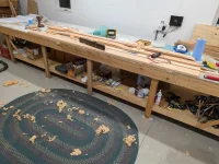
My shop was getting a little messy so I decided that it was a good day after being awake all night to not use any power tools and just work on cleaning up. The next day, I decided it was time to unload my build table so that I can prepare for building the upper wing on it.. The build instructions say to use saw horses, but my workshop is pretty full, so I am going to use my work bench. Yes I have room to get the wing out once built 🤣.

Ripped 3” strips of leftover ply to build spars on work table spaced to instructions locations. Added two more strips for centre section to have spars clamped to perpendicular supports…these will get removed from table after spars re splice together as they will be in the way of ply sheeting the centre.

I checked to make sure everything is flat. Later in the wing build instructions I will work out the difference in height between the centre of the front bar in the centre of the aft spar so that when when the leading edges gut glued on, the wing is flat, but that isn’t needed until the end of upper wing build…

I used my Hilger and Watts inclinometer to check the flatness of the plywood strips with a long level… but sometimes old methods are the most precise… so pulled a string from one end of the table to the other to check to see how all the positions relate to each other in flatness… even though the Hilger and Watts was shown pretty much dead nuts the string was able to show the thickness of the string out of alignment over the 22 feet. I am fascinated by how plumbobs, gravity, and strings can build precision machines. And for the sharp eyes, the roll of string is in fact clamped to the edge of the table and pulled tight enough that the string is about to break, but not quite; the C-clamp is just well hidden.

After shimming a few of the ply strips to get them level with each other, everything got fastened down to the table and I’ll be ready to start slicing spars together. But that’s going to be a story for next week as it’s family time weekend.

PXL_20260710_014914400_Original.webp
PXL_20260710_015030892_Original.webp
PXL_20260710_023208386_Original.webp
PXL_20260710_021559009_Original.webp
PXL_20260710_030110728_Original.webp
PXL_20260710_030438933_Original.webp
 
Hot in the shop today..Got the -3 spar scarf joints tuned to fit the -2 spar center section better.

Worked on making sure the assembly is flat tip to tip.

Hole drilling tomorrow morning when cooler.

PXL_20260714_014219680_Original.webp
PXL_20260714_165208691_Original.webp
IMG-20260714-WA0001_Original.webp
PXL_20260714_162521438_Original.webp
PXL_20260714_162652785_Original.webp
PXL_20260714_171758249_Original.webp
 
Last edited:
Man it is easy for me to start questioning my set up….is the table really flat? is the thickness of the string flat enough? After talking to all these people, am I still using the correct wood..blah blah blah…

Screw analysis paralysis, just keep going till you find a screw up! 😎

Committed…holes drilled in splice. The -2 center section has 2 holes in it to start the process. The splice of the -3 outboard sections reference a distance from the center of the -2 section, set up checked and checked again…The splice pieces seem to fit good after minor shaving with router and hand plane…holes drilled 15/64 using a drill guide and -28 HP wing splice part as template after first two -2 holes drilled, holes then opened up to 1/4 using drill guide, and then 1/4 pins installed. Holes will get varnished later and will require reaming after.

Lots of talk online about whether or not to keep the holes at 15/64 and varnish then Reem or go to 1/4 inch and varnish and ream… just something else to think about and not actually do anything until later so I just decided to go with quarter inch because those are the pin sizes I have..


The splice parts come extra tall and will be cut to fit the height of the spar prior to glueing…


I have exhausted my clamp collection; neighbour is a wood worker and has a large assortment he said I can borrow…Great to have a like minded fellow near by…

Things I have learned…yes my thick skull likes to come up with an untried solution, but I thought I had seen this, so repeated someone else’s idea thinking it would work. My set up on a shop table vs using saw horses like HP wing instructions is a butt pain for seeing the fitment of the spar spices. Yes with sawhorses you would have to crank your head around, but at least you have the ability to have a good luck without having to devise a way of getting your camera to take a picture of the bottom of the splice. An inspection mirror would be handy.

Secondly. I used two layers of plywood to raise the spar up off the table, however, if you’re going to end up using your build table for your wings, I would recommend using at least four layers of plywood to raise your spar up off the table, so that all your clamps fit underneath easier.

I know that many people that build these things professionally use saw horses, however, I find having mine on the table lets me put things down and pick things up a heck of a lot easier… I guess the professionals would have a rolling work cart beside there sawhorses to put everything on or something … I’m not just slapping these things together. I’m taking my time trying to fit and put clamps here, and splice pieces there…. little hand planning here a little thinking about what I’m doing there.

2wings.com still has the best pictures in the “Wings, Wing Pic Pac”.

PXL_20260715_184259261_Original.webp
PXL_20260715_185105393_Original.webp
PXL_20260715_185839078_Original.webp
PXL_20260715_194544250_Original.webp
PXL_20260715_210327999_Original.webp
PXL_20260715_211758769_Original.webp
PXL_20260715_214630919_Original.webp
 
Last edited:
Back
Top